

Seal Replacement Instructions Series 40, 50 and 60 Pump/Motor
Important Safety Notice:
Proper service and repair is important to the safe reliable operation of all hydraulic components. The service procedures recommended by Cross Manufacturing and described in this service manual are effective methods for performing service operations. Some of these service operations require the use of tools specially designed for the purpose. The special tools should be used when and as recommended.
It is important to note that some warnings against the use of specific service methods that can damage the hydraulic component or render it unsafe are stated in this service manual. It is also Important to understand these warnings are not exhaustive. Cross Manufacturing could not possibly know, evaluate and advise the service trade of all conceivable ways in which service might be done or of the possible hazardous consequences of each way. Consequently, Cross Manufacturing has not undertaken any such broad evaluation. Accordingly, anyone who uses a service procedure or tool which is not recommended by Cross Manufacturing must first satisfy himself thoroughly that neither his safety nor component function will be jeopardized by the service method he selects.
Disassembly:
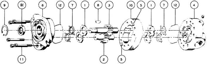
- Remove unit and thoroughly clean. Remove shaft key (8) and any nicks or burrs on shaft.
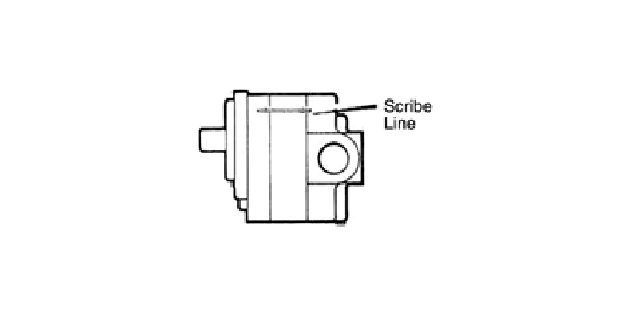
- Scribe line on outside of unit across front cover, body and rear cover to assure proper reassembly.
- Lightly clamp rear cover (4) in vise, shaft up. EXCESSIVE CLAMPING PRESSURE CAN CAUSE DISTORTION.
- Remove cap screws (11) from front cover (6). (Nuts on series 60).
- Tap upwards, underneath front cover flange and remove front cover. As unit separates, the body may remain with either the front or rear cover. Remove loose parts (rings, plates, etc.)
- *To separate body from front cover, clamp body in vise and again tap upwards on front cover flange. To separate body from rear cover, clamp body in vise and tap downward on shaft. Remove static seals (12) and loading seals (7) from grooves. DO NOT DAMAGE GROOVE OR COVER SURFACE.
- Remove snap ring (9) from shaft seal cavity in front cover using internal snap ring pliers.
- Clamp front cover in vise, seal down, and drive shaft seal out of cavity using screwdriver held at about a 45° angle. USE CAUTION NOT TO DAMAGE CAVITY.
*Step 6 can be by-passed if only the shaft seal is being replaced.
Parts Inspection:
- Thoroughly clean all parts in solvent and dry with compressed air.
- Inspect all parts for damage and unusual or excessive wear. If gears, bushings or body are damaged or badly worn, replace unit (Only plates and seals are replaceable).
Reassembly:
- Install new shaft seal (*) in front cover (6). Be sure bearing drain hole is not blocked.
- Install snap ring (9) and new seals (7,12) in covers (if needed).
- Assemble body (10) and rear cover (4) aligning dowel pins (5) and scribed line.
- Insert thrust plate (1) into body (10) flat side toward seal 7. Lubricate gears and insert.
- Insert thrust plate (1) over shaft, flat side toward seal 7.
- Lubricate shaft and slide front cover (6) over shaft and dowel pins (5). Tap if needed.
- Insert cap screws (11) (or nuts) and tighten evenly as follows:
- Series 40: 35/40 ft. lbs.
- Series 50: 35/40 ft. lbs.
- Series 60: 65/80 ft. lbs.
- Rotate shaft, the maximum torque is:
- Series 40: 15 ft. lbs.
- Series 50: 20 ft. lbs.
- Series 60: 25 ft. lbs.
It is the policy of Cross Manufacturing, Inc. to improve its products whenever possible and practical to do so. We reserve the right to make changes, improvements and modifications at any time without incurring the obligation to make such changes, improvements and modifications on any equipment sold previously.